20kN UTM - Universal Testing Machine TTM-20
20kN UTM - Universal Testing Machine TTM-20 is designed for analyzing the static properties of materials through tensile, compression, bending, shearing, peeling, tearing, loading, relaxation, and reciprocating tests. It supports both metal and non-metal materials, including composites. The system automatically calculates key parameters such as ReH, ReL, Rp0.2, Fm, Rt0.5, Rt0.6, Rt0.65, Rt0.7, Rm, and E. It conducts tests and generates data in compliance with ISO, ASTM, and DIN standards.
- Calibration of load measurement instruments for uniaxial testing machines
- Verification and calibration of static uniaxial testing machines
- Tensile testing of metallic materials at room temperature
- Tensile property determination for plastics
- Test methods for ceramic tile adhesives
- Mechanical performance requirements for metal profiles with thermal barriers
This ensures reliable, accurate, and internationally recognized testing results.
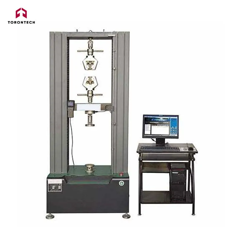
Mechanical Framework and Design
The main frame features a door-frame structure consisting of a base, two fixed beams, a movable crosshead, four columns, and two screws.
The transmission loading system uses an AC servo motor and a synchronous cog belt speed reducer to drive a high-precision ball screw, ensuring smooth movement of the crosshead for controlled loading.
Key advantages include:
- Sleek design
- Excellent stability
- High rigidity
- Precise control
- Efficient performance
- Low noise operation
- Energy-saving and eco-friendly functionality
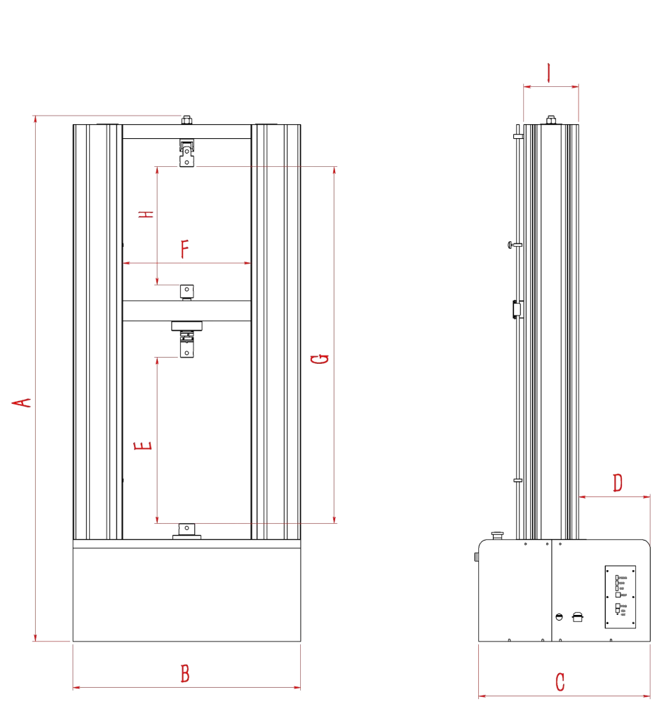
| Mark | A | B | C | D | E | F | G | H | I |
|---|---|---|---|---|---|---|---|---|---|
| Value (mm) | 1822 | 790 | 594 | 248 | 576 | 440 | 1237 | 410 | 190 |
Control and Measurement System
This machine features the advanced DSC-10TT full-digital closed-loop control system for precise control and measurement. A computer-based interface manages the testing process, providing real-time curve visualization and data processing.
After testing, users can zoom in on curves, reanalyze data, and edit results using the built-in graph processing module. The system ensures high performance, accuracy, and reliability, meeting international standards.
- Advanced Closed-Loop Control – Supports displacement, deformation, and speed closed-loop control, allowing real-time adjustments to testing speed and methods for greater flexibility.
- Comprehensive Safety Protection – Includes software and hardware protections, preventing overload, overcurrent, overpressure, undervoltage, overspeed, and limit breaches to ensure safe operation.
- High-Resolution Data Processing – Utilizes three high-speed 24-bit A/D conversion channels, achieving a resolution of ±1/300,000 for consistent precision throughout the test.
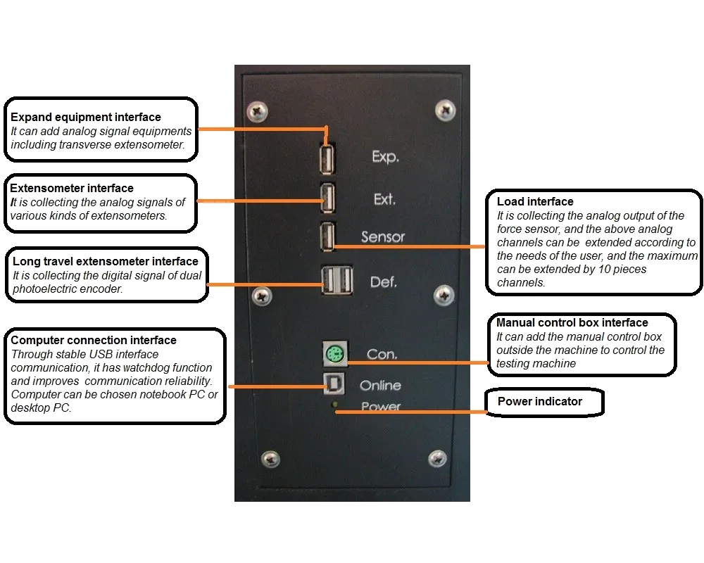
- Stable & Reliable Communication – Supports USB or serial communication, ensuring steady data transmission with strong interference resistance.
- Enhanced Signal Processing – Features three pulse signal capture channels (one for displacement, two for large deformation) and quadruple frequency technology, increasing effective pulse count by four times and achieving a maximum capture frequency of 5MHz.
- Precision Servo Control – Incorporates a digital-driven servo motor, with a PWM output frequency ranging from 0.01Hz to 5MHz, ensuring highly accurate control.
Key Benefits of the Control and Measurement System
1. Advanced Control System
The DSC-10TT full-digital closed-loop control system is a next-generation solution developed for precision testing machines. It integrates the latest servo motor control chips and a multi-channel data collection and processing module, ensuring high-speed sampling, accurate control, and system stability. The hardware-based design enhances reliability and consistency in performance.
2. High-Efficiency Professional Control Platform
The DSC-TT system combines DSP (high-speed computation) and MCU (strong I/O control), delivering superior performance compared to single DSP or 32-bit microcontrollers. Built-in motor control modules such as PWM and QEI ensure stable and secure system operation.
3. Parallel Hardware-Based Sampling
The system features an ASIC chip that enables synchronous sampling of load cells signals, eliminating asynchronous errors between loading and deformation measurements. This hardware-based parallel sampling ensures precise data collection and consistency.
4. Position Pulse Signal Filtering
The optical encoder module includes a 24-stage hardware filter, which shapes and filters pulse signals to prevent counting errors caused by interference. This guarantees accurate positioning and reliable pulse signal processing.
5. Optimized Control at the Core Level
Specialized ASIC chips handle sampling, condition monitoring, and communication, allowing the main system to focus on PID control. This hardware-level PID processing ensures faster response times, high stability, and optimized closed-loop control, making real-time adjustments seamless and efficient.
Performance Characteristics of DSC-10TT
The user interface supports Windows operating systems, offering real-time curve display and processing with graphical visualization. Its modular software structure enhances flexibility, while data storage and processing are managed through an MS-ACCESS database, ensuring seamless integration with Microsoft Office for efficient reporting and analysis.
The system features a graded user authority management mode, granting access based on user roles. The super administrator has full control and can assign different operation modules to users. It offers robust testing management, allowing flexible test unit settings, customizable testing programs, and automatic report generation based on selected standards. The system provides comprehensive curve analysis, supporting multiple curve types, real-time display, zoom-in analysis, feature point labeling, and comparative evaluations.
Test data is automatically stored to prevent loss and can be retrieved through a fuzzy search function. Users can merge and analyze test data from different timeframes, ensuring efficient comparison. The MS-ACCESS-based database allows seamless integration with Microsoft Office, enabling reports to be saved in Word and Excel formats.
The software automatically calculates test parameters such as ReH, ReL, Rp0.2, Fm, Rt0.5, Rt0.6, Rt0.65, Rt0.7, Rm, and E, with customizable parameters and graphical report printing. The system can detect when an extensometer is no longer needed and alerts the user accordingly. Additional automated features include crosshead return to the initial position, automatic calibration of load and elongation, and flexible measurement range selection. The modular unit design supports easy accessory exchange and hardware maintenance, while the automatic switch function dynamically adjusts display curves based on test force and deformation.
| Measurement Parameters | |
|---|---|
| Maximum test force | 20kN / 4496.18 lb.f(can add load cells to extend the force range) |
| Accuracy class | 0.5 |
| Measuring range of test force | 0.2%~100%FS (full scale) |
| Indicating error of test force | Within ±0.5% of indicating value |
| Resolution of test force | ±1/300000 of maximum test force, grade unchanged and resolution unchanged in whole process |
| Measuring range of deformation | 0.2%~100%FS |
| Indicating error of deformation | Within ±0.5% of indicating value |
| Resolution of deformation | 1/300000 of maximum deformation |
| Indicating error of displacement | Within ±0.5% of indicating value |
| Resolution of displacement | 0.025μm |
| Control Parameters | |
| Adjustable range of force control rate | 0.005~5%FS/s |
| Control accuracy of force control rate | When rate is less than 0.05%FS/s, within ±2% of setting value; When rate is no less than 0.05%FS/s, within ±0.5% of setting value. |
| Adjustable range of deformation rate | 0.005~5%FS/s |
| Control accuracy of deformation rate | When rate is less than 0.05%FS/s, within ±2% of setting value; When rate is no less than 0.05%FS/s, within ±0.5% of setting value. |
| Adjustable range of displacement rate | 0.001~500mm/min |
| Control accuracy of displacement rate | When rate < 0.5mm/min, within ±1% of setting value; When rate ≥ 0.5mm/min, within ±0.2% of setting value |
| Other Parameters | |
| Effective Testing Width | 440mm |
| Effective distance of tension | 610mm (including wedge tensile fixture and can be custom-made according to user’s requirements) |
| Removable distance of crosshead | 970mm |
| Size of Main unit (length x width x height) | (820×620×1880) mm |
| Weight of Main unit | 350Kg |
| Voltage | 220V, 50Hz, 0.75kW (110V is also available) |
Configuration
-
Main Unit: 20kN Door Structure
- Frame of whole machine: TTM series frame – one set
- Ball screws: High-precision and zero clearance – two pieces
-
Control System and Measuring System
- Servo motor, servo speed regulation, and control system – one set
- Synchronous belt – one set
- Load cells: 20kN load cells– one piece
- DSC-10TT full digital closed-loop measuring and control system – one set
- Load measuring system
- Displacement measuring system
- Deformation measuring system
- DSC-10TT English software
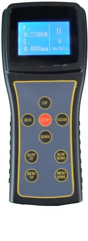
- Remote Control Unit (with LCD screen, real-time display of equipment running status, testing force, and displacement, with magnetic adsorption for flexible positioning) – one piece
- PC (Lenovo) – one piece
- Printer (HP color ink-jet A4) – one piece
-
Grips (Customizable as per requirements)
- Wedge tensile Grips (jaw size: flat 0-7mm; V Ф4-Ф9mm) – one set per size
- Compression Plates (plate diameter Ф100mm) – one set